CS 395/495 IBMR-- Project C:
Light Probe as a Panoramic Camera
Goals:
1) Warp a 2D image into several 3D
panoramas. Your program
will:
--- Read in a mirror ball or 'light probe' image, either from
those supplied or one you made yourself (I will have mirror spheres you
can borrow on Monday)
--- Find all the non-mirror-ball parts of the image and move
them out of the way,
--- Warp the image into the 3D half-sphere shape that mimics
the surface of the mirror ball,
--- Warp the half-sphere to form a full 3D sphere panorama,
--- Warp the sphere to make a cube panorama.
--- Optional: viewer for images encoded in spherical or
cylindrical coordinates.
2) Experiment with P3 camera notions to prepare for full 3D
descriptions of cameras and objects.
Step-By-Step Instructions:
1) Build on your ProjB code, or Download the 'starter' code I wrote for you
(and will continue to refine), see Project A assignment for a detailed
description, or the comments in the file quikGL.h.
4/29/03 Latest Revision: ProjA_17.zip Includes
matrix classes (in IBMRvecmat.cpp,.h) that include Singular Value Decomposition
matrix invert, and Gauss-Jordan elimination.
2) Remove Display Transformations applied to Mesh: Currently, the CquikMeshImg::drawMe() function
accesses a 3D textured mesh
made of quadrilaterals with vertices placed within the unit square:
(0,0,0) <= (x,y,z) <=(m_xTexmax, m_yTexmax, 0), then uses openGL calls to
transform this mesh to an on-screen position centered on the -Z
axis, and scaled so that its largest dimension (either x or y) spans +/-0.5 and
it's z value is z= -1. Remove the openGL calls that make these
display-only transformations of the vertices, so that vertex positions are
correct.
2) Set Mesh Vertex Positions Properly: Next, modify the code in CquikMeshImg::makeTestImgMesh() so that the mesh
vertices are created at the desired display positions (e.g. centered on
the -Z axis, and scaled so that its largest dimension (either x or y) spans
+/-0.5 and it's z value is z= -1). Once this works, modify the CquikMeshImg::fileLoad() so that it also
creates mesh vertices at the desired display positions. HINT: allow the
entire file to load using the existing code, then modify the positions of
vertices it creates for you.
3) Be sure Texture is still OK: Make sure that you can still load and
display a 'BMP' file at this point: try loading
some of the mirror-ball image examples in this ZIP file: mirrorBallBMP.zip. The loaded image should
be centered on the x3 axis where x3 = z = -1.
4) Write key-press handlers: Add new keyboard response functions
for 'V' (view) and 'W' (warp) into your program. Create a new
'viewing state' variable in your program, and increment it modulo-2 (e.g.
0,1,0,1,...) every time a user presses the V key. Similarly, make a new
'warp state' variable as well, and increment it modulo-3 (e.g.
0,1,2,0,1,2,0,...) every time the user presses the 'W' key. You will then use
the view state and warp state value to select how to display and warp images.
5) Create new 'View' choices: When the viewing state variable is
zero, keep the same viewing method we used
before--the camera's center of projection ('the viewing point') is
initially at x,y,z = (0,0,+viewctr), (where viewctr is usually 2.5) and dragging
the mouse rotates the camera around a world-space origin. When the viewing state
is 1, the view is different; it places the camera's center of projection at the world-space
origin (0,0,0), and mouse dragging should, as before, rotate us around the
origin.
The user's viewing parameters
are initialized by CquikGL::onSize_GL() -- look for the openGL command that
translates the camera to '-viewctr'; this call makes the origin (where we see
the x1,x2,x3 axes) visible within our field of view. Remember that 'onSize_GL()
is only called when the window is created or the user re-sizes the window.
You may also wish to add other
viewing states of your own; use the V key to select the current viewing state.
6) Make new 'Warp' choices: When the warp state variable is zero, do
the 'null' warp--the CquikMeshImg object is displayed as it always is, with
vertices of the CquikImgMesh object in the z=-1 plane, centered along the z
axis. It is warp states 1, 2 and beyond that are interesting:
--Hemisphere Warp: Hemisphere warp: see step 6A, 6B below
--Panoramic Sphere Warp: see step 6C below
--Panoramic Cube Warp: see step 6D below
--Spherical, Cylindrical Warp(Optional): Add the ability to
view spherical and cylindrically encoded images in your program without
distortion. These rectangular input images map x-direction distance to
azimuth angle (rotation about z-axis, longitude) and y-direction maps to
elevation. Cylindrical coordinate images map y to elevation distance, as an
ordinary image does; spherical coordinate image map y to elevation angle (e.g.
lattitude on a sphere).
7) Try several Light-Probe Images: Look around on the Web to find an
interesting light probe image, make your own light probe image, or use example
light probe images from this zip file: mirrorBallBMP.zip
Viewing from the origin, does your Light Probe Panorama warp give you an
undistorted view of mirror-ball's surroundings? If not, you may have
errors in your code. Move the viewpoint away from the origin, and make a
screen-capture of your program's displayed result after it performs the
Hemisphere and Light Probe Panorama warps. Include these 'results'
pictures when you turn in your completed project.
8) Turn in Your Project: Please follow the instructions found here: Homework
Instructions
Other Light Probe Images and related links:
There are many mirror-ball images available on the web, and it is not hard to
make your own, either; I have ordered 4 chrome spheres that you may borrow to do
your own experiments; please check them out from the TA Abhinav Dayal.
Here are a few interesting links: two from a Czech
student project, are various artists collections like this one (Cylindrical
Panorama Page), from an artist's
site who used PanoTools to get an 'equirectangular' image that appears to be
a spherical mapping, with several to
choose from here.
Paul Debevec also has an online library of light probe images. Note that
these are high-contrast, floating-point images on his site, but he has a nifty
downloadable viewer for these files. At this
site, Johnathan Cohen of ICT uses light probes as inputs and finds synthetic
light source intensities and locations that will reasonably simulate the lights.
Someone has written a
Photoshop plugin for mirrorball images, complete with a tutorial on how to
remove the photographer from the scene by photographing the ball twice, from 2
different angles.
Panorama tools 'PanoTools'
written in Java; worth playing with; I think they originate with Dersh
here!
Some cylindrical panoramas from
Germany present a sphere-like object on-screen.
Warp Instructions:
---6A) Matte: Find all the image vertices that are not a part of the
mirror ball, and move them inwards to the circular boundary of the mirror ball
as seen within the image Note that most mirror-ball images are square and
cropped so that the circular boundary of the mirror ball is inscribed within the
image boundaries--it touches the outer edge of each side of the image.
---6B) Half-Sphere Warp: Construct a half-sphere by moving
vertices in the
light probe image.
For each mirror-ball vertex,
a) Convert rectilinear image grid coordinates (x,y)
to polar coordinates (r, theta) in the image.
b) Convert these polar coordinates to spherical
coordinates of the mirror ball. For simplicity, assume the mirror-ball
image is orthographic, e.g. that rays from the camera to the mirror ball surface
are parallel, so the distance from the mirror ball to the camera that
photographed it doesn't matter, and center the sphere at the origin.
Thinking in 3D now, convert (r,theta) to spherical coordinates on the
mirror ball (phi,theta), where phi is latitude and theta is longitude (phi=0 at
the north pole, pi at the south pole). Remember that when r=0 we have a
zero-diameter circle on the image that matches a zero-diameter circle around the 'north
pole' of the sphere. Increasing radius r from zero corresponds to
increasing 'longitude' phi from zero on the mirror ball sphere; find the mapping
from r to phi.
c) Move the vertex in 3D; place it at angular position
(phi,theta) on a sphere around the origin. You'll need to figure out how
to convert spherical coordinates (phi,theta,r_s) to Cartesian coordinates (x,y,z).
Now the previously planar grid image
has become a textured half-sphere shape in 3D: its colors are the image colors mapped to the mirror ball points
that reflected them to the camera.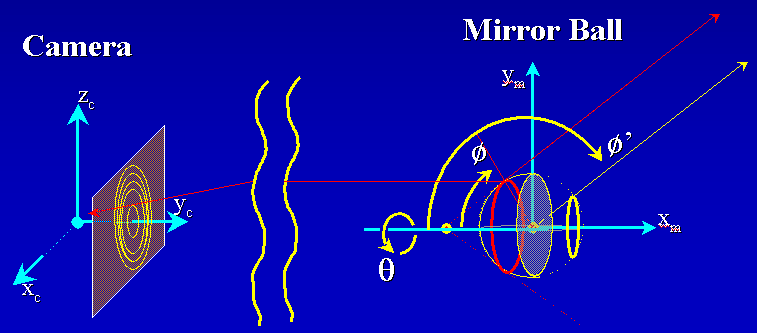
---6C) Panoramic Sphere Warp: Move the vertices again to change
a half-sphere we made previously to a full sphere panorama:
For each mirror-ball vertex,
a) find the vertex position in spherical coordinates (or just
remember it from step 3) as (phi, theta, r_s).
b) Though the vertex hold colors that were SEEN on the mirror
ball at this position, it these light values did not arrive at the mirror ball
from the (phi,theta) directions from the environment. As
discussed in class, the incoming light direction is phi'=2*phi, and theta,r_s
are unchanged. Accordingly, find the new 3D position (phi',theta,r_s) for
each vertex.
c) Convert to x,y,z position, and move the vertex there.
Now your previously planar grid image
has become a textured sphere shape, perhaps with a funny little 'dent' at the back where
vertices not on the mirror sphere have collected at the origin.
---6D) Panoramic Cube Warp: Move the vertices again to change a
sphere to an axis-aligned cube:
For each mirror-ball vertex,
a) Use its (x,y,z) coordinates to determine its cube
face. Test the coordinates to do this; results of (|x|>|y|),
(|y|>|z|), (|z|>|x|) and sign of x,y, or z will determine whether to put
the point on the front (x=+1), back(x=-1), top(z=+1), bottom(z=-1) etc.
b) Move the point radially outwards from the sphere center to
its position on a cube face.
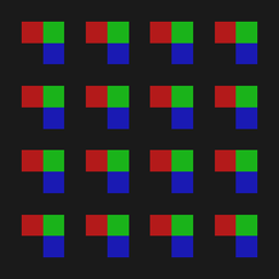
Test Images:
You may wish to test your program using these simple grid-like test images to
help understand the geometric changes made by your program.

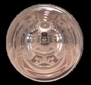
Example Results Images: (from Abhinav Dayal's 2002 IBMR class assignment)
Input image texture-mapped onto a square mesh that encloses a unit circle
placed in x3=1 plane.
Vertices outside the light probe image were moved
to the origin. (Last year's assignment was slightly different). Viewpoint
is at x3 = +3.5.
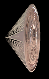
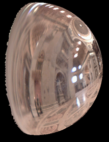
Results of half-sphere warp around the origin. Note how non-lightsphere
vertices are bunched at the origin.
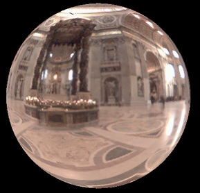
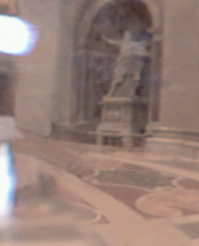
Results of a panoramic sphere warp; First image is seen from x3= +3.5, and
sphere was rotated slightly (compare with input image). Second image is the view
from inside the sphere, looking outwards from the origin. Note view from
inside is looking back towards the camera, and statue's extended arm on left is
extended rightwards in the reflections shown in the light probe images above.
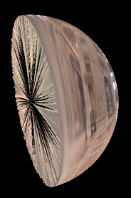
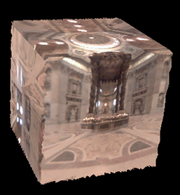
Results of a panoramic cube warp. Note that each side of the cube is a
planar perspective image. Jagged edges are normal here; vertices are not
aligned with cube edges.
Thanks to Abhinav Dayal for his beautifully written software from last
year's class!
Last Modified: 05/13/2003
Jack Tumblin